ECD guide
The Electron Capture Detector (ECD) was invented by James Lovelock and specifically designed to detect electrophilic compounds. The detector captures electrons from a radioactive source when electronegative analytes pass through. This gives high sensitivity, in the picogram range, for halogenated and other electron absorbing compounds.
How does the detector work ?
A beta radioactive source which can ionize the carrier gas is located in the detector. A current is produced between two electrodes which is monitored as the background current. When
there are electro-negative components present in the carrier gas, the background current is reduced due to these components capturing electrons.
The radioactive Nickel-63 foil releases beta radiation. The beta radiation ionizes the nitrogen gas creating a cloud of free electrons. These free electrons are drawn towards the anode,
generating a steady current. When a sample containing electron absorbing analytes is introduced, these analytes capture some of the free electrons. The capture of the electrons reduces the number of electrons reaching the anode, which decreases the current. The current decrease is measured at the signal probe and results can be viewed using the CompassCDS software.
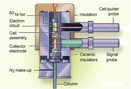
Figure 1: Inside of the ECD
The detector works only with nitrogen or argon/methane gas as make-up gas. Helium can be used as the carrier gas only and hydrogen cannot be used. Typically when a higher sensitivity is necessary, Ar/CH4 can be used. The sum of the make-up and carrier gas flows should total between 20-30 mL/min.
The ECD is primarily used for analysing analytes which contain halogens and nitriles. It is a high sensitivity detector and can detect analytes at concentrations in the picogram range.
Tuning of the ECD with CAP
Before testing the ECD should be tuned. This is an example tune when using capillary columns (CAP). To tune the ECD follow the steps below:
- Turn on the make-up gas, set the ECD to 300 °C and set the column oven to 150 °C.
- Via the GC-LUI set the Cell Current to Zero.
- Set the RANGE to 10.
- Via the GC-LUI set the Contact Potential to -760mV.
- Turn Electronics ‘ON’ (via tickbox) and un-click AUTOZERO.
- Check that the signal is between -127.0 mV and -135.0 mV.
- Now set the Contact Potential (C.P.) to (+) 760 mV.
- Allow the signal value to respond.
- Now adjust the Contact Potential back in the negativedirection until the value is ±5.0 mV away from its original value. For example: if the signal was -129.0 mV, adjust the contact Potential until the signal reads -124.0 mV.
- Set the Cell Current to “CAP”.
- Let the signal stabilize for at least 8 hours before proceeding.
- After the stabilization period the ECD will usually have ‘drifted’ away from its correct C.P.-setting. Therefore, the Contact Potential should be checked and probably re-adjusted.
Maintenance
The ECD contains a radioactive source so it must be handled with care and following any risk assessments which are in place.
To change the column follow the steps below:
- Turn the electronics OFF. Cool down the ECD below 100°C.
- OFF the make-up and carrier gas flows. Uninstall the column and install the new column.
- Let the ECD bake-out for one hour or preferably overnight at 300 °C.
- Tune the ECD.